Jet grouting involves the erosion of the soil by cement grout, jets of water, and/or compressed air, and the mixture of the grout with the soil to form grouted columns or walls. The grout pipe with jets may be self-drilled or inserted into a predrilled hole. The jetting fluids are pumped at high pressure while the pipe is withdrawn with rotation for columns or without rotation for walls.
Jet grouting’s ability to construct soilcrete in limited spaces and around subsurface obstacles such as utilities, provides unique design flexibility. In any situation requiring control of groundwater or excavation of unstable soil (water-bearing or otherwise) jet grouting is often a preferred solution.
![]() See more our jet grouting and deep soil mixing projects
See more our jet grouting and deep soil mixing projects
 See our scientific database to learn more about jet grouting and deep soil mixing…

Constructed Jetgrouting columns view
The procedure for jet grouting operation typically includes the following steps:
1. Position the drilling machine at a desired location for injection.
2. Drill into the ground to the desired depth. The tolerance of the drilling location should be less than 50 mm.
3. Insert the jet grouting pipe to the predrilled grout hole. Some machine installs the jet grouting pipe directly with an auger at the tip.
4. Once the pipe reaches the desired depth, start the jet grouting process by withdrawing the pipe and injecting grout until reaching a desired elevation. The operation should follow the specifications for injection pressure, injection rate, injection time, pipe withdrawal rate, and pipe rotation rate.
5. Clean up the injection pipe and other associated tools.
6. Move to the next jet grouting location.
During Jet grouting procedure, high pressure flow of cement grout erodes soil body and makes a soil-cement combined column that can improve mechanical properties of soil.

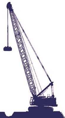
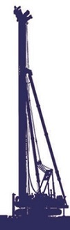
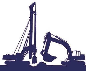
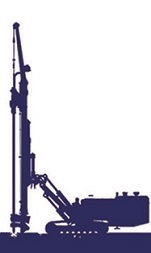
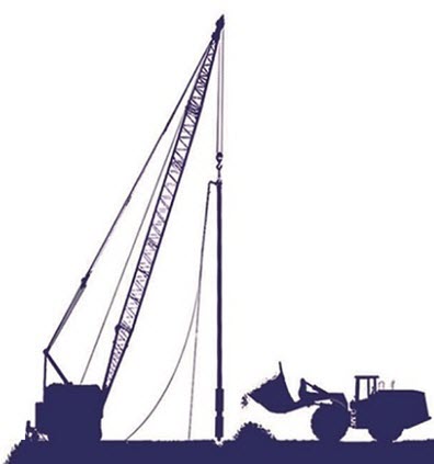
Water jet and drilling equipment
Selection of Jet System
The single jet system injects neat cement grout through a small nozzle at high pressure, which is mixed with in-situ soil. This method produces the most homogeneous soil–cement columns or walls with the highest strength and the least amount of grout spoil return. It is the simplest system among the three systems and has more choices of qualified specialty contractors.
The double jet system injects neat cement grout at a lower pressure, which is aided by a cone of compressed air. The air reduces the friction loss and allows the grout to travel a farther distance to produce a greater column diameter. However, the presence of the air reduces the strength of the column and produces more spoil return than the single jet.
The triple system injects water at high pressure, which is aided by a cone of compressed air. This process produces an air lifting effect, which erodes the soil. The grout is injected at a lower pressure through a separate nozzle below the water and air nozzles to fill the void created by the air lifting process.

Different systems of jet grouting

Different interaction mechanisms of soil and jet flow

Different systems of jet grouting
Design principles
Jet grouting columns are used to increase bearing capacity, control settlement, mitigate liquefaction potential and reduce soil permeability. In order to reach to aforementioned goals jet grouting columns can be designed like piles. For instance toe and skin friction resistance of jet grouting columns should be considered in design procedure and their capacity will be determined based on their geotechnical and structural capacity.
Structural capacity is determined using unconfined compression strength of soilcrete samples. Unconfined compresion strength of soilcrete can be obtained from 28-day samples taken from sacrificial columns.
According to following figure, Unconfined compression strength of soilcrete samples is dependent to consumed amount of cement.
| Soil Type | Single fluid | Double fluid | Triple fluid |
|---|---|---|---|
| Sandy soils | 10-30 | 7.5-15 | 10-20 |
| Clayey soils | 1.5-10 | 1.5-5 | 1.5-7.5 |
Unconfined compression strength of improved soil with jet grouting method MPa (Kauschinger et al., 1989)

Unconfined compression strength of jet grouting columns vs. consumed cement
Application:
Jet grouting is a widely used method of soil improvement and can be acceptable in various soil conditions. Jet grouting has been used for the following applications:

Application of jet grouting method comparing to other methods
Quality control and assurance:
The general procedure for quality control and assurance are similar to that for deep mixing. Quality control for grouting may include the following steps:
Quality assurance includes the following field testing:
Advantages and Limitations
Jet grouting has the following advantages as compared with alternate technologies:
The limitations associated with grouting are:

Combination of jet grouting columns and ground anchors
The deep mixing (DM) method mixes in-situ soil with a hardening agent (cement, lime, slag, or other binders) at depths by augers. Deep mixing can be accomplished by a wet or dry method. The equipment for the wet method may have one to eight rotary hollow shafts with cutting tools and mixing blades above the tip. The binder slurry is introduced into the ground through each hollow shaft and exits from the nozzle while the shaft penetrates into the soil or is withdrawn. Some equipment has mixing blades rotating in opposite directions (i.e., double mixing) to improve the uniformity of the soil–binder mixture. The equipment for the dry method may have single or dual rotary shafts with cutting tools and mixing blades above the tip. The binder powder is introduced into the ground through each hollow shaft and the nozzle by air pressure.

Deep soil mixing columns
Design principles
The design procedure for deep mixing is similar to jet grouting columns design and also depends on the type of application. For foundation support, the following design procedure may be followed:

Design and construction flowchart of Deep soil mixing method
Construction procedure
The basic DM procedure by the wet method is illustrated in Figure. This method includes:

Construction stages of deep soil mixing
Applications
Columns have been used for many applications in soft soils:
Deep mixed columns have also been used for roadway widening to support new embankments and mitigation of ground heave due to expansive soil. In these applications, DM columns are used to increase bearing capacity, reduce settlement, enhance slope stability, provide lateral support, contain water and pollutant movement, mitigate liquefaction, and reduce vibration.

Application of deep soil mixing
Quality Control and Assurance
The typical quality control (QC) and quality assurance (QA) procedure for deep mixing is presented in Figure. It starts with the design or targeted strength of a stabilized soil. Laboratory mix design tests should be performed to determine the binder content to reach the targeted strength. Sometimes, field trial is implemented to verify the field strengths of test columns. During the installation, all the parameters for deep mixing should be well controlled, including binder content. After the installation, the quality of columns should be confirmed by sampling, coring, and in-situ testing. Field instrumentation and monitoring may be conducted for large and/or complicated projects. Quality control and quality assurance can be achieved by evaluating the installation records of the columns and the test results of laboratory and field verification tests. Each column installation record should include a chart-log with the construction information, such as date and time of execution, length of column, penetration/withdrawal rates of the mixing shaft, blade rotation rate, pressure and flow rate of pumped slurry or injected powder, and total slurry or powder consumption per column.

Geometry control of deep soil mixing columns

Quality control and assurance procedure
Micropiles and Underpinning